Can Brightness Augmentation Imitate a Lighting Change? — Generalizing Edge Models with a Multi-Condition Capture Matrix
EDGE AI / ALGORITHM
An edge model trained on dents and scratches of machined aluminum parts sometimes suddenly loses performance after the light bracket is retightened or the equipment is moved to the next line. This happens even though ample brightness, gamma and noise augmentation was included at training. Tracing the cause usually shows that what changed was not the brightness of the illumination but the illumination angle.
Miss this difference and the cost appears as a retraining loop. While re-imaging, re-labeling and redeployment repeat on the floor, a period of reduced inspection reliability appears, and in the meantime some defects pass undetected depending on the direction of the dent. Worse is the case where the decision threshold is raised to cut the increased overkill, and misses of the finest scratches quietly increase.
The solution is to first separate the changes augmentation can reproduce from those it cannot. Brightness, gamma and noise augmentation imitate changes in pixel values, but a change in illumination angle is a change in spatial structure — the direction of shadows and the position of specular reflection. The latter can enter the training data only through a multi-condition measured capture matrix taken while actually changing the illumination conditions.
Brightness augmentation changes values; illumination angle changes positions.
1. What Per-Pixel Augmentation Cannot Reproduce — Shadow Direction
Point. Brightness, gamma and noise augmentation are all per-pixel transforms, and per-pixel transforms cannot move the direction of a shadow.
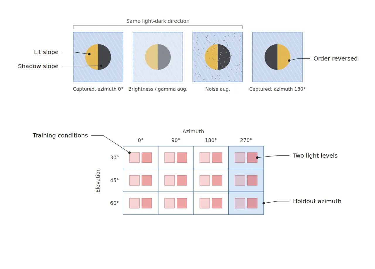
Reason. Brightness augmentation has the form I′ = aI + b and gamma augmentation I′ = Iγ, so each pixel’s new value depends only on that pixel’s original value. Moreover, brightness transforms with a > 0 and gamma transforms are monotonically increasing functions, so they cannot reverse the brightness order of two pixels. Noise augmentation also only adds independent fluctuation per pixel and does not move structure. Under low-angle directional illumination, by contrast, a dent is recorded as a light-dark pair in which the slope facing the light is bright and the opposite slope is dark, and when the illumination azimuth changes by 180° the left and right of this pair swap. The order reversal in which bright pixels become dark and dark pixels become bright cannot be produced by any monotonic transform.
Example. Applying brightness ±20%, gamma 0.8 to 1.25 and Gaussian noise σ = 2 DN (8-bit basis) to dent data captured only under 0° azimuth illumination changes lightness and graininess from image to image, but the direction of the light-dark pair stays fixed in every sample as “bright on the light side, dark on the opposite side”. The model learns a dent as “a light-dark pair in this direction” and sees a dent under the 180° condition as a different pattern. Horizontal flip augmentation can partly imitate the direction, but it also flips the direction of the machining lay (tool marks), creating images that do not actually exist.
Point. When building an augmentation list, first ask “is this change a change in pixel values, or a change in positions?” Changes in position must be secured by capture, not by augmentation.
2. Specular Highlight Shift — A Bigger Problem on Metal Surfaces
Point. On machined metal surfaces, the positional shift of the specular highlight shakes the model more than shadows do.
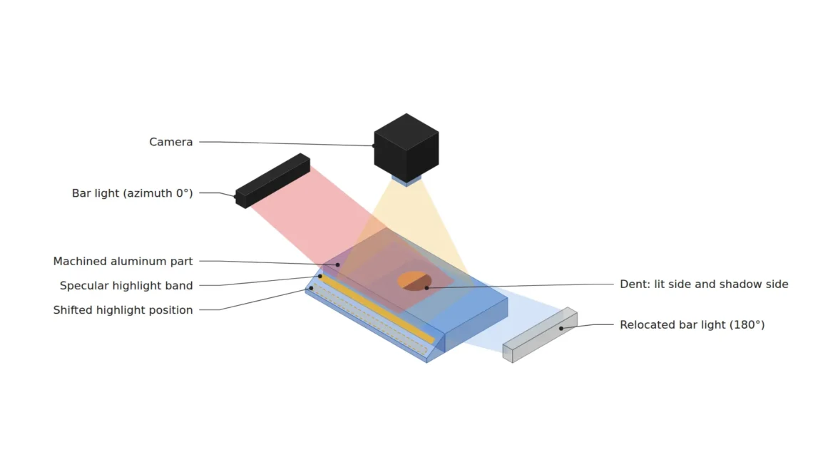
Reason. Specular reflection returns strongly only in the direction where the angle of reflection equals the angle of incidence, so where the highlight lands in the image is decided by the geometry of the light position, camera position and surface normal. Even a small change in illumination elevation moves the highlight band along a curved surface, and a defect that was there is either buried in the saturated region or, conversely, newly revealed. A saturated pixel holds no defect information in principle, so there is nothing software can revive at that spot.
Example. Imaging an aluminum part with a chamfered curved surface at 45° illumination elevation places the highlight band in the middle of the chamfer, and lowering it to 30° moves the band to a different position on the chamfer. A model trained only on 45° data remembers “the bright band in the middle of the chamfer” as part of normal appearance, so under the 30° condition it may see the spot the band moved to as an anomalous pattern. Darkening or brightening the band with brightness augmentation leaves its position unchanged. On such surfaces where high reflection and diffuse reflection mix, the shift depends on machining roughness and curvature, so it cannot be confirmed before sample testing.
Point. For metal parts, the mounting tolerance of the light bracket is itself part of the training data distribution. The angle range that mounting tolerance can produce must be included in the capture conditions.
3. Designing a Multi-Condition Measured Capture Matrix
Point. Generalization to changes in illumination angle is obtained not by raising augmentation strength but by designing a capture matrix with illumination conditions as its axes.
Reason. Mixing many conditions without a plan only increases the capture volume, and it becomes impossible to know which conditions support performance. Designed as a matrix, the condition axes (elevation, azimuth, light level) are explicit, so training and validation can be split by condition. In particular, validation must use condition-level holdout (leaving one entire azimuth out of training and evaluating on it), not random splitting, to actually measure generalization to unseen illumination conditions. With random splitting, neighboring samples from the same condition enter both training and validation, and performance is overestimated.
Example. As a design assumption, with 3 illumination elevations (30°, 45°, 60°) × 4 azimuths (0°, 90°, 180°, 270°) × 2 light levels = 24 conditions, and 40 good plus 20 defective parts captured per condition, the total is 1,440 images. Because the light-level axis can be partly replaced by brightness augmentation, if the capture budget is short, the priority is to start with 12 conditions and 720 images by reducing light levels to one, while not reducing the angle axes. The edge model is trained on this data, and brightness, gamma and noise augmentation are kept only in a supporting role that fills light-level deviation between conditions and sensor noise.
Point. A capture matrix is a data collection plan and at the same time a specification of illumination mounting tolerance. If the light is installed at an angle outside the matrix, that condition is one that has not yet been validated.
Random-split validation cannot measure performance under illumination the model has never seen.
4. Core Framework — Matching Table
| Category | Item | Specification / Parameter | Basis · Notes |
|---|---|---|---|
| ① Minimum defect size | Scratch | Width 45 µm or more | Design assumption. Approx. 3.0 px at 14.9 µm/px (detection floor) |
| ① Minimum defect size | Dent | Diameter 100 µm or more | Design assumption. Approx. 6.7 px, about 3 px for each side of the light-dark pair |
| ① Minimum defect size | Chamfer burr | Length 150 µm or more | Design assumption. Approx. 10 px, including the highlight shift zone |
| ② Optical setup | Illumination | Low-angle directional bar lights in 4 azimuths, adjustable elevation 30°/45°/60° | Machined aluminum mixes high and diffuse reflection. Cannot be confirmed before sample testing |
| ② Optical setup | Camera | 4096 × 3000 px, 3.45 µm pixel | Design assumption. Sensor width approx. 14.1 mm |
| ② Optical setup | Lens | Focal length 35 mm, magnification approx. 0.23× | Calculated: 14.1 mm ÷ 61 mm |
| ② Optical setup | WD (working distance) | 160 mm or more must be secured | Calculated object distance approx. 186 mm (from principal plane). Measure including mounting space for 30° elevation bar lights |
| ② Optical setup | FOV · pixel resolution | FOV 61 mm × 45 mm, 14.9 µm/px | Calculated: 61,000 µm ÷ 4,096 px ≈ 14.9 µm/px |
| ③ Algorithm | Per-pixel augmentation | Brightness ±20%, gamma 0.8 to 1.25, noise σ 2 DN | Supports light-level deviation and sensor noise. Cannot replace angle changes |
| ③ Algorithm | Capture matrix | Elevation 3 × azimuth 4 × light level 2 = 24 conditions, 60 images each, 1,440 total | Design assumption. If budget is short, reduce the light-level axis first |
| ③ Algorithm | Validation split | Azimuth-level holdout, 4 runs (360 images per run) | Report alongside random-split results to see the overestimation |
| ③ Algorithm | Input | 48 tiles of 512 × 512 px (8 × 6), no downscaling | Premise of keeping the original pixel resolution |
Table takeaway. At 14.9 µm/px, a 45 µm scratch is about 3.0 px, sitting at the detection floor, so it is the class that disappears first when an illumination angle change lowers contrast even slightly. Of the 1,440 images in the capture matrix, one azimuth accounts for 360 images (3 elevations × 2 light levels × 60 images), forming one holdout validation run, and how far scratch recall on these 360 images falls compared with random splitting shows numerically the generalization margin for “illumination never seen before”.
5. When the Opposite Approach Wins
- When the illumination is tolerance-controlled by a fixed jig and the target is a diffuse surface: Angle changes hardly occur, so single-condition capture with per-pixel augmentation may be sufficient. The cost of a capture matrix becomes excessive.
- When surface reflection properties can be measured and rendered: Measuring a reflection model (BRDF) and generating synthetic images can partly replace angle changes with synthesis. However, measuring and validating the reflection model costs extra.
- When omnidirectional diffuse illumination such as a dome light can be used: Removing the directionality of shadows and highlights in hardware may be cheaper than a capture matrix. In exchange, the light-dark contrast of dents also weakens.
On surfaces where diffuse and specular reflection mix, such as machined metal, the range of appearance change with illumination angle depends heavily on machining roughness and curvature, so the number of capture conditions needed cannot be confirmed before sample testing.
Field Note
In appearance inspection of machined parts just ahead of a high-speed assembly line, after an equipment relocation the bar light bracket was reassembled at an angle lower than 45°, and overkill on the chamfer suddenly increased. The training data had plenty of brightness and gamma augmentation, but the position the highlight band moved to had never been learned. After introducing azimuth-level holdout validation, I was able to confirm that the performance seen under random splitting dropped sharply only for a particular azimuth. How many capture conditions are enough differs with each part geometry, so even now I capture a sample matrix first for a new part before judging.
Field Checkpoints
- Is a WD of 160 mm or more secured by measurement — verify including the mounting space for 30° elevation bar lights and bracket interference.
- Has the surface material and reflectance of the target been identified first — the highlight shift range differs with machining roughness and chamfer curvature.
- Has each item in the augmentation list been classified as a “change in values” or a “change in positions”.
- Does the angle range that the light bracket’s mounting tolerance can produce fall inside the capture matrix.
- Is validation performed with condition-level holdout rather than random splitting.
- Does the 45 µm scratch occupy 3 px or more, and is recall in the highlight shift zone tallied separately.

Noctvision
A machine vision engineer who fits cameras, lenses, lighting, and image-processing algorithms together for a living. Years spent on continuous production lines, vibration, heat, and dust included, working through diffuse reflection, contrast, and resolution differences too fine for a spec sheet to capture inform every post here, closing the gap between theory and the shop floor. Off duty, that same eye for light and lenses goes into repairing fully mechanical vintage film cameras.


You May Also Like
Camera Interface Bandwidth Determines Resolution — From GigE Vision to CoaXPress 2.0
Four Snags in Initial Jetson Orin Nano Setup