An 850 nm Band-Pass Filter Erases Factory Lights but Leaves Sunlight
LIGHTING
An 850 nm band-pass filter all but erases factory LED lighting yet keeps sunlight, and what remains shrinks with how many times harder the light is driven, more than with the exposure time.
For a 5 MP mono camera reading a carbon-ink code on a color label, I calculated the ambient swing, the absorption depth in silicon and the diffraction blur at each aperture.
About 15 min read
If the same label shot at ten in the morning and at four in the afternoon gets two different decisions, what should you suspect? On the inspection table sits a molded part with a color-printed label, and on that label a lot code printed in carbon ink. The label surface mixes matte and glossy printing, so it scatters most of the light, yet on glossy ink there are spots where the light bounces off in one direction.
The cause usually lies outside the inspection light. Sunlight through a window, the ceiling lights and the work lamp of the next machine sway the brightness of the sample plane from hour to hour, and the camera takes that light in together with the inspection light without telling them apart. Set the decision line in the bright hours and false rejects rise in the dim hours; set it the other way and codes with missing dots blend into the color pattern and pass.
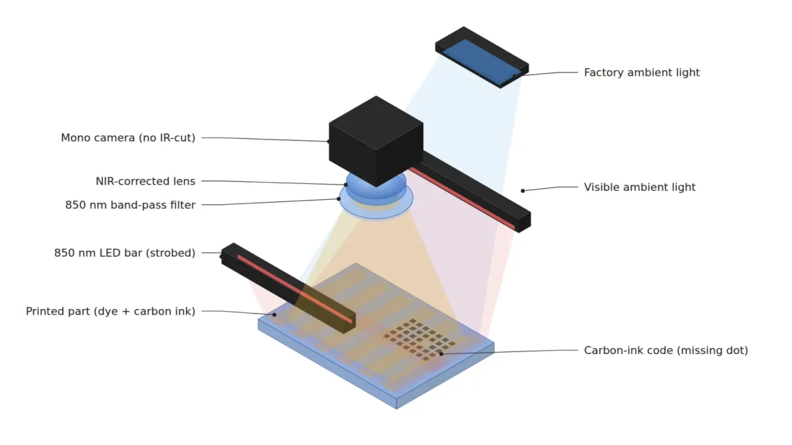
Instead of fighting the ambient light with a brighter lamp, I would move the inspection to 850 nm in the near-infrared1, where there is little ambient light, and let the camera see only that wavelength. The calculations assume a 5 MP mono camera without an IR-cut filter (2,448 × 2,048 px, 3.45 μm pixels), fitted with a 25 mm lens corrected for the near-infrared and viewing 80 mm across. One pixel covers 32.7 μm, and the WD2 from the lens principal plane to the label is about 262 mm.
The light that sways the decision comes from outside the inspection light
The value of a pixel is the sum of all light that arrived during the exposure. Inside that value, the share made by the inspection light and the share made by sunlight through the window cannot be told apart. For the calculation, take the label background at 200 gray levels and a carbon dot at 60 under the inspection light alone, and assume the sunlight rises and falls by 40 levels, 20 % of the background, over the day.
With the decision line halfway between background and dot at 130 levels, there are 70 levels of margin on each side. On the numbers alone, a 40-level swing seems to fit within the margin, but sunlight is not added equally to the background and the dots. On glossy ink the sunlight bounces toward the lens and a single dot can turn as bright as the background, and the color pattern sends back a different share of sunlight for each color, so the background itself shifts in patches. Even when the average swing of 40 levels stays inside the line, local spots can exceed 70 levels.
That is why the same decision line is right in the morning and wrong in the afternoon. Changing the line for each hour only chases the symptom, so I choose to split the light before it reaches the camera. There are three axes to split it along, wavelength, time and space, and the three work by multiplication, so each one divides what the others leave.
At 850 nm some inks vanish and others stay
The first thing to check before moving the wavelength is the label material. Ink containing carbon black absorbs light evenly from the visible into the near-infrared and stays black at 850 nm, while many dye-colored inks absorb a particular color strongly in visible light yet turn almost transparent in the near-infrared. That is why, in an 850 nm image, the color pattern fades or disappears and only the code printed in carbon stays dark.
Once the pattern disappears, a missing dot becomes an empty spot on an even background and the decision gets simple. If the code itself was printed with dye ink, though, the code disappears at 850 nm as well, so before choosing the light and the filter, I would take one picture of the same label with a near-infrared flashlight and a camera with its IR-cut filter removed, and see what remains. A thin translucent cover colored with dye can let more light through in the near-infrared and reveal foreign matter underneath.
How much near-infrared light an ink or dye absorbs varies by formulation, and glossy printing mixes diffuse and specular reflection, which changes the share of reflected light too. Which patterns vanish and which codes stay cannot be guaranteed before a sample test. Only for a label that has passed this check do the filter calculations carry any meaning.
A filter blocks only light of other wavelengths
Mount a band-pass filter3 centered at 850 nm with a FWHM4 of 50 nm in front of the lens, and the camera receives only light near 825 to 875 nm. Just as tuning a radio dial to one station lets you hear only that station, the filter lets in only light near the set wavelength. The figure below shows which light stays inside that window.
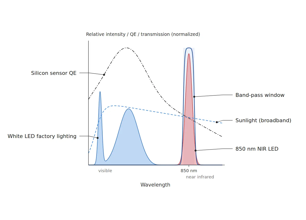
In the figure, the white LED factory lighting has both its narrow peak and its broad peak inside the visible range, so almost none of it passes the 850 nm window. Sunlight is the problem. It spreads widely from the visible into the near-infrared and leaves its share inside the window too, and a filter cannot block light of the same wavelength. Assume 5 % of the sunlight seen by an unfiltered camera stays inside the window, and the 40-level swing shrinks to 2 levels; the share of the white LEDs is taken as close to zero and dropped from the calculation.
The sensor pays the price. The quantum efficiency5 of a silicon sensor peaks in the visible range and falls toward the near-infrared, so at 850 nm it sits well below the peak, as the dashed line in the figure shows. How far below depends on the sensor and is read from the spectral response curve in the datasheet; here it is assumed to be 40 % of the peak, so getting the same 200 levels takes 2.5 times the light. Most color cameras carry an IR-cut filter and receive almost no near-infrared, so a mono camera without that filter is chosen, and focus is set with the 850 nm light switched on.
What a shorter exposure buys equals the overdrive factor
On the time axis the arithmetic runs against intuition. Cut the exposure from 10 ms to 1 ms and the time for sunlight to build up also drops to a tenth, so the ambient light seems to shrink, but the inspection light drops by the same ratio and the ratio between the two stays the same. The inspection light share and the sunlight share in a pixel value are both proportional to the exposure time, so the only thing that changes the ratio is how strong the light is during the exposure.
Shoot it shorter
and cutting the exposure to a tenth seems to cut the sunlight share to a tenth as well.
Worked out as a ratio
the inspection light drops with it, so the ratio stays the same. Only the overdrive factor changes the ratio: drive the light 10 times harder and it gets 10 times better.
So a short exposure helps only when paired with a strobe6. Assume the light allows overdrive7 at 10 times, running the LED briefly at a current several times its continuous rating: at a 1 ms exposure the image comes back to the same 200 levels as continuous lighting at 10 ms, and the ratio of inspection light to sunlight improves 10 times. The swing already cut to 2 levels by the filter now falls to 0.2 levels. The detailed calculation for pulse width and overdrive factor is in freezing motion blur with strobe overdrive.
What happens if the exposure goes down to 200 μs? With the same 10 times overdrive the ratio still improves 10 times, and the image gets five times darker, leaving 2.3 stops to make up with gain or aperture. For a label shot while it stands still, I choose 1 ms. The case for 200 μs is freezing the blur of a moving part, and that condition brings in the transport side, which needs a separate review.
Overdrive comes with a duty cycle8 limit. Assume a light that allows 10 times overdrive only at a duty cycle of 1 % or less: 1 ms pulses then cap the rate at 10 frames per second, and 200 μs pulses at 50 frames per second. The actual allowed factor and duty cycle come from the datasheets of the light and the driver, and for a light without that table, overdrive stays out of the calculation. Running past the duty limit heats the LED, which lowers its brightness and shortens its life, so a station that needs more frames per second lowers the overdrive factor and writes the smaller ratio gain into the calculation as it is.
Silicon takes 850 nm light five pixels deep
The near-infrared takes one more price on top of brightness. The absorption depth9, at which light inside silicon falls to 1/e, is 1.56 μm at 550 nm but 18.7 μm at 850 nm, twelve times deeper. That depth is more than five times the 3.45 μm pixel width, so charge created deep down spreads to the neighboring pixels as crosstalk10, and even the same sensor records softer edges.
The blur grows on the lens side too. The diameter of the Airy disk11 created by diffraction is 2.44 × wavelength × f-number, so at 850 nm and f/8 it spreads to 16.6 μm, or 4.8 pixels. Projected onto the label that is a 157 μm blur, and a 100 μm wide scratch, narrower than the blur, loses much of its contrast. At the same f/8 the disk is 10.7 μm at 550 nm, so moving to the longer wavelength means opening the aperture by more than one stop for the same sharpness. My standard is an Airy disk no wider than three pixels, so I pick f/4 with 8.3 μm, or 2.4 pixels, which still leaves a depth of field12 of 5.5 mm, enough for a flat label.
Software can hardly undo this blur. A sharpening filter only boosts whatever contrast is left; it cannot put back charge that has already crossed into the next pixel or light scattered by diffraction, so in a near-infrared setup the aperture and the pixel size are chosen together from the start.
Reading 150 μm dots, and the labels this setup does not suit
The swing shrinks by multiplication at each step. With no countermeasure, the sunlight swing of 20 % of the background falls to 1 % behind the band-pass filter and to 0.1 % after 10 times overdrive, and in gray levels it becomes the three numbers below.
40levels
the sunlight swing with no countermeasure
2levels
behind the band-pass filter, 5 % inside the window assumed
0.2levels
after adding 10 times overdrive
Set these three numbers beside the 70-level margin around the 130-level decision line, and the filter alone already brings the swing below 3 % of the margin, while overdrive cuts that share by another factor of ten. Collect the wavelength, filter, exposure and aperture on one spec sheet and it comes out as below, with every pixel count based on one 32.7 μm pixel.
| Item | Value | Condition and basis | In plain words |
|---|---|---|---|
| ① Minimum defect size · missing carbon code dot | 150 μm diameter = 4.59 px (32.7 μm/px) | 80 mm across ÷ 2,448 px, empty blobs of 4 px or more | One dot covers four and a half pixels |
| ① Minimum defect size · foreign matter under a translucent cover | 200 μm diameter = 6.12 px | only where a dye-colored cover transmits more at 850 nm | Six-pixel objects seen through the cover |
| ① Minimum defect size · scratch on the print | 100 μm wide = 3.06 px | Airy disk 2.4 px at f/4, 4.8 px at f/8 with contrast loss | Three pixels wide, so the aperture stays open |
| ② Optical setup · light and filter | two 850 nm LED bars, band-pass centered at 850 nm with 50 nm FWHM | sunlight swing 40 → 2 levels (5 % inside the window assumed), white LED share taken as zero | Erase the light outside the window |
| ② Optical setup · exposure and overdrive | 1 ms exposure, 10 times overdrive, duty 1 % or less → 10 frames per second cap | swing 2 → 0.2 levels, brightness the same 200 levels as continuous 10 ms | Drive it harder and shorter to change the ratio |
| ② Optical setup · camera, lens and WD | 5 MP mono without IR-cut (3.45 μm), NIR-corrected 25 mm, f/4, WD about 262 mm (from principal plane) | 2.5 times the light with QE assumed at 40 % of peak, depth of field 5.5 mm, room for the filter holder and LED bar brackets inside the WD | Focus with the 850 nm light on |
| ② Optical setup · shielding | hood on the window side, light-off image average at or below 1 % of the background | blocks direct-sun glints on glossy ink | Shade the glints coming from the window |
| ③ Algorithm parameters · ambient subtraction | subtract the light-off image from the light-on image | a helper step that trims only what optics already reduced | Take out the leftover sunlight once more |
| ③ Algorithm parameters · flattening | flat-field correction from an 850 nm image of a white reference | corrects the illumination profile of the two LED bars | Erase the unevenness of the light |
| ③ Algorithm parameters · detection | missing dot: empty blob of 4 px or more against the grid; scratch: line filter σ 1.5 px | decision line 130 levels (background 200, dot 60 assumed) | Look for gaps and thin lines separately |
Following the swing column down the table shows the order that steadies the decision: the filter, then overdrive, then shielding. The average swing almost disappears in the first two steps, so the 70-level margin around the 130-level decision line is left untouched, and the remaining worry is local glints on glossy ink. That share is handled by the hood on the window side.
Some labels do not suit this setup. If color itself is the pass criterion, print color differences and coloring defects lose their information in an 850 nm monochrome image, so color imaging in visible light is the right choice. If the sharpness of the finest scratches comes first, shorter wavelengths win on both absorption depth and diffraction, and blue light can give crisper edges. In an open spot where no shielding can be built and sunlight falls directly, the sunlight share inside the window grows and the filter gains less. Which way is right depends on the label inks and the installation spot, so it cannot be guaranteed before a sample test.
The person who turns this multiplication into a spec sheet is the machine vision engineer on site. For someone starting to learn, I recommend filming the infrared LED of a remote control with a phone’s front camera and seeing for yourself that light invisible to the eye is visible to a sensor. From the side that plans the equipment budget, moving to the near-infrared means changing the light, the filter, the lens and the camera together, so the quote grows to four lines, while fewer hours go into resetting decision lines by time of day. This article explains technology and is not investment advice. See our Disclaimer.
Field Note
For a station whose decisions waver only around three in the afternoon, I would take one picture with the light off at that hour before fitting any filter. The average of that image as a share of the 200-level background is the share of sunlight that remains inside the window, and by the numbers of this setup it should come out under 1 % once the filter is in place. If the average is higher, I look for spots where direct sun glints on glossy ink and put up a hood on the window side. Whether the code ink stays visible at 850 nm gets one new picture each time the material lot changes.
Field Checkpoints
With the light-off number from the Field Note in hand, use the questions below to turn the setup into spec-sheet sentences.
- Do the band-pass filter holder and the LED bar brackets fit inside the WD of about 262 mm (25 mm lens, from the principal plane) without blocking the view? (distance from the lens front from the lens drawing)
- Have you first separated matte printing from glossy printing on the label surface? (sunlight glints on glossy ink)
- Have you confirmed on samples that the code ink that must stay is carbon based and that the pattern that must vanish turns transparent at 850 nm?
- Is the camera free of an IR-cut filter, and was focus set with the 850 nm light on?
- In the brightest hour of the day, does the light-off image average stay under 1 % of the background? (if higher, a hood on the window side)
- Have you confirmed the overdrive factor and duty cap in the light datasheet, and do the pulse and the exposure window line up?
- Is the aperture opened to about f/4 so the Airy disk stays within three pixels? (4.8 pixels at f/8)
Frequently Asked Questions
Wouldn’t going to 940 nm cut the sunlight further?
Sunlight has a stretch near 940 nm where water vapor in the air absorbs it, so it can help on the ambient side. In exchange, the absorption depth in silicon grows to 54.6 μm, close to three times that at 850 nm, and the sensor loses more quantum efficiency and sharpness. My approach would be to consider 940 nm only where no shielding can be built, and in that case to check the sensor’s quantum efficiency at 940 nm in the datasheet first. Rebuilding the lighting budget when the sensor changes is covered separately in the near-infrared budget of a BSI global shutter sensor.
If you subtract a light-off image from a light-on image, why bother with a filter?
Subtraction removes the average of the leftover sunlight but not the noise the sunlight brought with it. Subtracting two images adds the noise of each, making it √2 times larger, and the stronger the sunlight, the larger that noise. If the part moves between the two images, mismatched fringes also appear along the edges, so subtraction is kept for trimming the leftover that the filter and overdrive have already reduced.
Glossary
- [1] Near-infrared near-infrared, NIR
Light with a longer wavelength than the red the human eye can see. A silicon sensor picks up only the part of it up to about 1,100 nm. ↩ - [2] WD working distance
The distance from the lens to the inspected surface. Here it is a thin-lens value measured from the lens principal plane; the actual clearance from the lens front comes from the lens drawing. ↩ - [3] Band-pass filter band-pass filter
A filter that passes only a narrow band around a set wavelength and blocks the rest. It is matched to the light and mounted in front of the lens. ↩ - [4] FWHM full width at half maximum
The width of a transmission curve at half its peak height. A FWHM of 50 nm means a window open 25 nm to each side of the center. ↩ - [5] Quantum efficiency quantum efficiency, QE
The share of photons entering the sensor that turn into charge. It changes with wavelength, so datasheets print it as a curve. ↩ - [6] Strobe strobe
A way of switching the light on briefly in step with the camera exposure. Light builds up in the image only while it is on. ↩ - [7] Overdrive overdrive
Running an LED briefly at a current above its continuous rating to raise its momentary brightness. The on-time share is capped so heat does not build up. ↩ - [8] Duty cycle duty cycle
The share of each period during which the light is on. Ten frames per second lit for 1 ms each make 1 %. ↩ - [9] Absorption depth absorption depth
The depth at which light entering a material falls to 1/e, about 37 %, of its strength. The longer the wavelength, the deeper it reaches into silicon. ↩ - [10] Crosstalk crosstalk
Charge made by light in one pixel spilling over into the next pixel. It is one reason edges come out soft. ↩ - [11] Airy disk Airy disk
The round blur a single point spreads into as it passes through a lens, caused by diffraction. Its diameter to the first dark ring is 2.44 × wavelength × f-number. ↩ - [12] Depth of field depth of field, DOF
The depth range in front of and behind the focus distance that stays sharp. The values here assume a circle of confusion of 2 pixels (6.9 μm). ↩
References
- Formulas: pixel resolution = field of view ÷ pixel count, magnification m = pixel size ÷ pixel resolution, object distance = f × (1 + 1/m), Airy disk diameter = 2.44 × λ × N, depth of field ≈ 2 × N × c × (m + 1) ÷ m², light-to-ambient ratio = (light intensity × exposure) ÷ (ambient intensity × exposure), duty cycle = frame rate × pulse width
- Assumptions: 5 MP mono camera (2,448 × 2,048 px, 3.45 μm), 25 mm lens, 80 mm horizontal field, background 200 levels and dot 60 levels, sunlight swing 20 % of the background, 5 % of sunlight left inside the window, QE at 850 nm 40 % of peak, 10 times overdrive allowed at a duty cycle of 1 % or less, circle of confusion of 2 pixels (6.9 μm)
- Absorption depth in silicon (300 K): 1.56 μm at 550 nm, 18.7 μm at 850 nm, 54.6 μm at 940 nm. PVEducation, Optical Properties of Silicon. pveducation.org/pvcdrom/materials/optical-properties-of-silicon
Related reading — Changing the Sensor Means Recalculating the Illumination · Gaps in a Clear Conformal Coating Show Up Under UV Fluorescence · A Mono Camera Catches PCB Color Differences When You Choose the Wavelength

Noctvision
An engineer who has handled mechanical design and project management for production equipment since 2005. Here I work through the cameras, lenses and lighting that go into equipment with formulas and public data, and record the assumptions and sources alongside the numbers.


You May Also Like
On Thick Parts, Silhouette Measurement Error Comes from the Backlight’s Angle
Coaxial Light Alone Does Not Settle Fine Scratches on Polished Metal