In Automotive Part Appearance Inspection, Lighting Design Comes First
LIGHTING
Under a point source the brightness gap between chrome and black paint passes 70,000 times, but under a dome it falls to 12 times and fits in one frame.
On an automotive parts line mixing painted, chrome-plated and molded-trim surfaces, I calculated the brightness ratio under each lighting type and the angles at which defects light up.
About 10 min read
On an automotive parts line, surfaces with very different reflectance enter one frame. With the chrome plating of a door handle, body-color paint and matte molded trim side by side, one light struggles to suit all three. Lighting tuned for chrome sinks the paint into darkness, and lighting tuned for paint blows the chrome out to white, so either way the scratches and dents of one surface drop out of inspection. Those parts come back as quality claims after shipment. The fix is to settle the lighting for each surface first and put the algorithm on top of it.
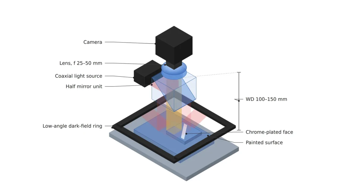
All the calculations use one setup: a 12 MP camera with 4,096 × 3,000 px and 3.45 μm pixels, fitted with a 35 mm lens. Seeing a 30 μm defect over 3 pixels takes 10 μm per pixel, which gives a 41.0 × 30.0 mm field and a WD1 of about 136 mm from the lens principal plane to the part.
Reflectance is assumed at 60 % for chrome plating, 5 % diffuse reflectance for the pigment of black paint, and 30 % for light gray molded trim. Real values change with plating thickness, paint and molding resin, so they have to be measured on samples.
Three surfaces return the same light in very different ways
Chrome plating is close to a mirror, so most of its return is specular reflection2, sending light back in one direction only. Matte molded trim returns mostly diffuse reflection3, scattering light in every direction. Paint stacks the two: the transparent clear coat4 on top reflects about 4 % of normally incident light like a mirror, and the pigment layer beneath scatters part of the rest in every direction to show the color. That is why the three surfaces come out at very different brightness under the same lighting.
The defects sought differ by surface too. On chrome and paint the targets are fine scratches and shallow dents; on molded trim they are flow marks and particles. By my rule, the defect list is split by surface first, the lighting that shows each defect best is chosen per surface, and only then is the number of shots per part decided.
Under a point source chrome is 70,000 times brighter than paint
Light the part with one small LED, and the LED shows up on the chrome as if in a mirror. The brightness of that hotspot is the LED emitter brightness times the reflectance, constant regardless of distance, while the brightness of black paint is the share of the LED light it scatters in every direction, falling with the square of distance. Assuming a 5 mm emitter 200 mm from the part, the ratio between the two is 0.6 × π × 200² ÷ (19.6 mm² × 0.05) = 76,800 times, 16.2 stops5.
A 12-bit camera holds 4,096 brightness levels, 12 stops. A 16.2-stop gap fits in one frame at no exposure, so keeping the chrome hotspot below saturation6 pins the black paint at 0, and saving the paint blows the chrome hotspot out to white. Even the painted surface alone has its 4 % clear-coat hotspot and 5 % pigment scatter 5,120 times, 12.3 stops, apart under a point source, already beyond 12 bits. A setup that shoots this part with a single point source fails at the calculation stage.
Make the light brighter
and it seems the dark paint will show up well too.
Calculated with a point source
the 76,800-fold ratio between the chrome hotspot and black paint stays the same however bright the light, so both cannot fit in the 4,096 levels of 12 bits.
A dome brings the ratio back to the ratio of reflectances
In dome illumination7, the whole inner wall of a hemisphere glows at the same brightness. Whichever way the chrome tilts, it reflects wall of the same brightness, and the light reaching the paint pigment also comes from the whole hemisphere, so the brightness ratio falls to the ratio of reflectances, 0.6 ÷ 0.05 = 12 times. At 3.6 stops it fits comfortably in 12 bits, and the ratio between chrome and light gray trim is only 2 times. For the same reason the clear-coat reflection on paint comes out close to the pigment scatter, and the hotspot disappears.
The price is clear too. With light coming from every side, shadows vanish, so defects that show only through height, such as gently sloped dents or flow marks, fade as well. The hole at the top through which the camera looks gives off no light, leaving a dark spot where the chrome reflects that hole, and the dome must come close enough to cover the part, so the WD and the dome diameter have to be matched together. When I use a dome, I first mark on the part drawing where that hole will be reflected. The size of that dark spot is calculated in the dome light dark-spot article.
Scratches show under low-angle light, dents under coaxial
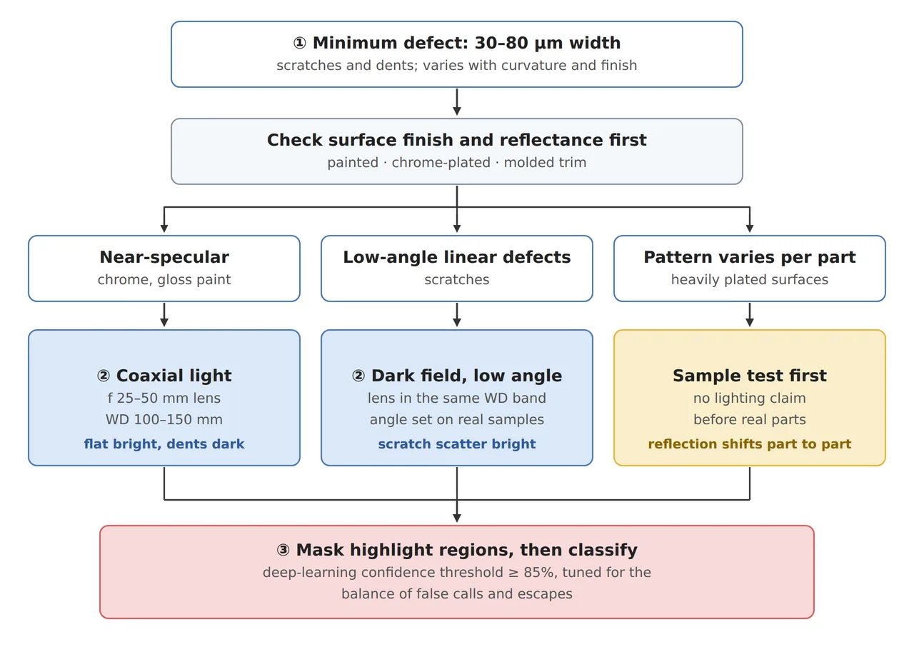
Fine scratches on paint are caught well by dark-field illumination8 from a low angle. Light coming in 15° above horizontal bounces off the flat clear coat at the same 15° on the other side and leaves in a direction 75° from the optical axis. Half the field angle of this setup is 8.5°, so none of it enters the lens and the background stays dark. Only facets tilted roughly between 33° and 42°, that is, the steep walls of scratches, send light into the lens, so scratches rise as white lines on a black background.
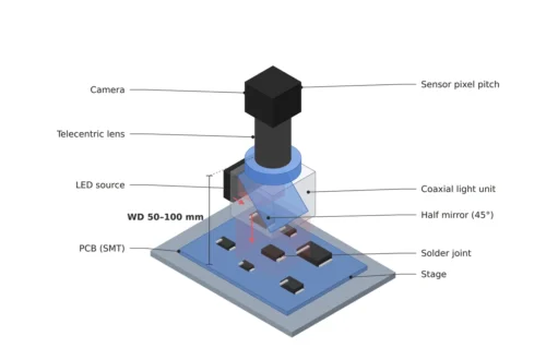
Gently sloped dents, in contrast, barely glow under low-angle light. For dents in flat chrome, coaxial illumination9 fits. Light coming down the optical axis returns from flat chrome straight into the lens and lights the background, while the slopes of a dent send light out of the lens and stay dark. Where it starts to darken is calculated with the tilt tolerance; with this lens’s aperture half angle of 1.3°, coaxial without a diffuser gives 0.66° and diffuse coaxial with ±10° spread gives 5.7°. The method follows the coaxial lighting calculation.
The 0.66° figure cuts both ways. Every slope steeper than 0.66° looks dark, catching even shallow dents, but if the part seated in the fixture tilts by just 0.66°, the whole background darkens. Diffuse coaxial tolerates fixture tilt up to 5.7°, but makes dents gentler than that as bright as the background. My approach for flat chrome zones is to measure the fixture tilt first and pick coaxial without a diffuser if it stays within 0.5°, or diffuse coaxial otherwise.
Splitting lighting zones by surface
Assigning the three lights by surface means shooting each part in three frames. The pixel coverage is 10 μm in every case, and what changes is the lighting and the inspection rules. With a 30 fps camera, three frames take 100 ms, and the part has to stay still during that time.
| Surface · defect | ① Minimum defect size | ② Optical setup · WD | ③ Algorithm parameters |
|---|---|---|---|
| Curved chrome · dents and particles | 30 μm = 3 px (10 μm/px) | dome light, 35 mm lens, WD about 136 mm from the principal plane, chrome to black paint 12 times (3.6 stops) | mark the dark-spot zone from the top hole as not inspectable, count pixels of 4,000 or more (12-bit) separately |
| Flat chrome · shallow dents | 30 μm = 3 px | coaxial light, no diffuser if fixture tilt stays within 0.5° (tolerance 0.66°), half-mirror housing inside the 136 mm WD | dark-spot detection, tilt alarm if background falls below 80 % of reference (example) |
| Paint · fine scratches | 30 μm wide = 3 px | low-angle light 15° above horizontal, only walls tilted 33° to 42° glow | bright-line detection, length filter, confidence threshold starting at 85 % and tuned |
Read together, the three rows show that each surface needs a different light to reveal its defects, so a setup that tries to finish in one frame gives up at least one of the three defects. The opposite approach has its conditions. If the part has only one surface, chrome, or the only defect to find is particles, one dome frame is enough, and on a line with no time for three frames, a compromise remains of firing the zone lights together in one frame. On parts whose chrome reflection varies from piece to piece, which way fits cannot be guaranteed before a sample test.
Algorithms work on the contrast the lighting creates
Deep learning classification learns the difference in texture between curved reflection patterns and real defects, and cuts false detections. But if the brightness difference between defect and background never makes it into the image, the model has no difference to learn. A saturated chrome hotspot or black paint pinned at 0 is a blank for any model. So instead of a mask that erases highlights, I count saturated pixels separately as not inspectable and set a rule to revisit the lighting when that area grows. The confidence threshold is set by which costs more, false detections or missed ones, a calculation covered in the overdetection versus missed detection article.
The work of a vision engineer handling automotive appearance inspection starts with splitting the defect list by surface and designing the lighting zones. For a beginner, shooting a chrome spoon and black plastic in turn under a flashlight and under a white umbrella is enough to get a feel for today’s calculation. From the investment side, an appearance-inspection quote is sized by the number of lighting zones and shots more than by the number of cameras. This article explains technology and is not investment advice. See our Disclaimer.
Field Note
If I take on this line, I seat a chrome part in the fixture and remove it ten times, recording the background brightness under coaxial light, to see first whether the fixture tilt stays within 0.66°. If the background swings widely from frame to frame, I move to diffuse coaxial and check how many pixels a dent specimen of known depth stays dark. For the paint, I place the low-angle light at 15° and 20°, shoot the same scratch specimen, and keep whichever gives the larger brightness difference along the line.
Field Checkpoints
To move the lighting zones per surface into spec-sheet sentences, answer the questions below.
- Does the dome or the coaxial housing fit inside the roughly 136 mm WD of the 35 mm lens without hitting the part? (a dome has to come close enough to cover the part)
- Are the defect list per surface and the lighting suited to each defect organized in one table? (for parts mixing chrome, paint and trim)
- Does the tilt of the part seated in the fixture stay within 0.66°, the tolerance of coaxial light without a diffuser? (otherwise use diffuse coaxial)
- Is the low-angle light about 15° above horizontal, with the reflection from flat surfaces landing outside the 8.5° half field angle? (whether the background stays dark)
- Are saturated pixels and pixels pinned at 0 counted separately as not inspectable? (an erased area is an uninspected area)
- Have you re-measured the brightness ratio on samples from lots with a new plating thickness or paint? (assumed reflectance 60 %, 5 % and 30 %)
Frequently Asked Questions
Can a polarizing filter erase the chrome reflection?
Metals such as chrome twist the polarization when reflecting at an angle, so they often do not block as cleanly as non-metal surfaces. The clear-coat reflection on paint is easier to reduce with polarizing filters, so cross-polarization is worth considering for the paint zones. The effect varies with the plating condition and needs checking on samples.
With an AI model, can’t the lighting be unified into one?
A model learns only the differences contained in the image. If chrome and black paint sit 76,800 times apart under a point source, one of them saturates or pins at 0 and the difference vanishes, and the defects in that area never reach the training data either. Match the lighting to each surface so the differences are in the image first, and the model can focus on cutting false detections on top of that.
Glossary
- [1] WD working distance
The distance from the lens to the surface being inspected. The values here use a thin-lens approximation from the lens principal plane; the distance from the lens front comes from the lens drawing. ↩ - [2] Specular reflection specular reflection
Reflection in which light bounces off a smooth surface in one direction only, at the same angle it came in. Chrome plating returns most of its light this way. ↩ - [3] Diffuse reflection diffuse reflection
Reflection in which light scatters back in every direction from a rough surface or a pigment layer. It looks about equally bright from any direction. ↩ - [4] Clear coat clear coat
The transparent resin layer on top of a paint finish. With a refractive index around 1.5 it reflects about 4 % of normally incident light like a mirror. ↩ - [5] Stop stop
A way of counting light in steps of two. The 4,096 levels of a 12-bit camera correspond to 12 stops. ↩ - [6] Saturation saturation
The state in which a pixel has reached the brightest value it can hold and can no longer tell brighter light apart. It shows up as a blown-out white area. ↩ - [7] Dome illumination dome illumination
Lighting in which the whole inner wall of a hemisphere glows evenly and wraps the part from every side. The camera looks in through a hole at the top. ↩ - [8] Dark-field illumination dark-field illumination
Lighting from a low angle so that the reflection from a flat surface misses the lens. The background stays dark and only the walls of scratches glow. ↩ - [9] Coaxial illumination coaxial illumination
Lighting sent down along the camera optical axis by a half mirror. Flat glossy areas look bright and tilted slopes look dark. ↩
References
- Formulas: hotspot to background under a point source = specular reflectance × π × distance² ÷ (emitter area × diffuse reflectance), reflection to background under a dome = specular reflectance ÷ diffuse reflectance, Fresnel reflectance = ((n − 1) ÷ (n + 1))², tilt of facets that glow under low-angle light = (90° − elevation ∓ half field angle) ÷ 2, coaxial tilt tolerance ≈ (lens aperture half angle + light spread) ÷ 2, object distance = f × (1 + 1/m)
- Assumptions: 12 MP camera (4,096 × 3,000 px, 3.45 μm pixels), 35 mm lens at f/5.6, 10 μm per pixel, reflectance (chrome 60 %, black paint pigment 5 %, gray trim 30 %, clear coat 4 %), LED emitter 5 mm in diameter at 200 mm, 12-bit output, diffuse coaxial spread ±10°, 30 fps
Related reading — Six Machine-Vision Lighting Methods and How to Choose · For Scratches on Highly Reflective Metal, Choose the Lighting First · The Cost of Switching Between Dark-Field and Coaxial with Software-Defined Lighting

Noctvision
An engineer who has handled mechanical design and project management for production equipment since 2005. Here I work through the cameras, lenses and lighting that go into equipment with formulas and public data, and record the assumptions and sources alongside the numbers.


You May Also Like
Can Five Defect Samples Stand Up a Few-Shot Anomaly Detection Line?
In the Age of Deep-Learning Inspection, What to Check Before Camera Spec