What to Write First in a Machine Vision Spec Sheet — The Order and Checklist for Choosing Camera, Lens and Lighting Specs
OPTICS / LIGHTING
A request for quotation (RFQ) for vision inspection equipment often starts with a camera pixel count and adjectives such as “high speed, high precision”. Each supplier imagines a different setup from that sentence, and the quotes come back under conditions that cannot be compared. One sets a wide FOV, another leaves out the lighting, another writes the processing time as an average.
When the specification starts from component specs instead of the defect definition, it is only at commissioning after delivery that you learn the minimum defect covers less than 3 px or the lighting cannot beat the surface reflection. By then the only thing that can change is the algorithm threshold, not the hardware already ordered, and while the threshold is adjusted, yield loss and escape risk pile up between over-detection and missed detection.
The fix is to change the order of the spec sheet. Filling it in the order defect definition → resolution → optics → lighting → capture conditions → interface and processing → acceptance conditions derives each item by calculation from the one before, so conditions become the same across suppliers. This article lays out the seven-step order and, as a checklist, the items and units to write at each step.
A spec sheet should start not with a camera name but with the size of the smallest defect to detect and the surface material.
1. Defect Definition and Surface Material — The Inputs to Every Calculation
Point. The first page of the spec sheet states the minimum size (µm) for each defect type and the material and reflective properties of the target surface.
Reason. Resolution, lens, lighting and exposure conditions are all calculated from these two values. Once the minimum defect is set, the required resolution (minimum defect ÷ 3) follows, and whether the surface is specular or diffuse splits the candidate lighting methods.
Example. Writing only “no scratches” lets each supplier interpret it by its own standard. Writing “scratches of 20 µm width and 300 µm length or more, polished aluminum (specular)” narrows the candidates to about 6 µm/px resolution and coaxial-type lighting (the setup example in the coaxial illumination article on polished metal). Supplying limit samples (OK/NG boundary samples) with it reduces interpretation differences further.
Point. If defect size and material cannot yet be written as numbers, sample evaluation comes before ordering equipment. For strongly diffusing materials in particular, it cannot be guaranteed before a sample test.
2. Resolution, FOV and Optics — Items Derived by Calculation
Point. Pixel count and lens go into the spec sheet as “derived values”, not “required values”.
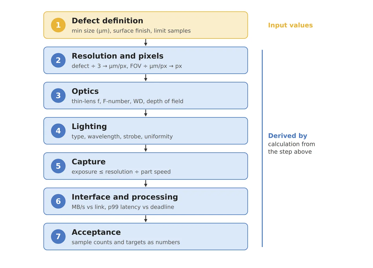
Reason. Resolution = minimum defect ÷ 3, required pixel count = FOV ÷ resolution, and the focal length is back-calculated with the thin-lens formula. Adding the WD and the part height variation (the depth-of-field requirement) decides the lens type — an ordinary lens or a telecentric one.
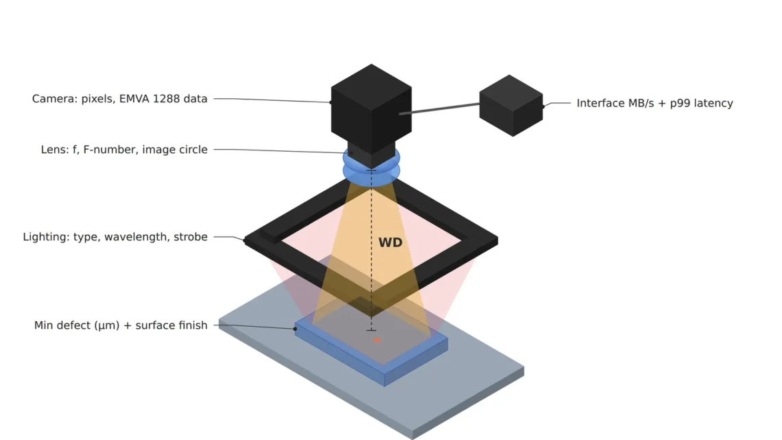
Example. To see a 100 µm defect in a 100 mm FOV, you need 33.3 µm/px or finer and at least 3,000 px across. Writing this in the spec sheet as “at least 3,000 px across, WD of at least ○○ mm, minimum defect kept at 3 px over a height variation of ±○ mm” lets you compare the camera and lens combinations suppliers propose on the same basis. If the cameras themselves must be compared, asking for measurement data in the EMVA 1288 format (quantum efficiency, dark noise, saturation capacity, dynamic range and so on) instead of each maker’s own figures makes it easier to align conditions.
Point. If items derived by calculation are written like required values, you lose the means to check whether a supplier matched the defect definition or merely matched that number.
3. Lighting and Capture Conditions — Speed Sets Exposure, Exposure Sets Light
Point. For lighting, write “conditions” rather than a “type” — candidate methods, wavelength, continuous or strobe, exposure time limit, uniformity.
Reason. If the part is imaged while moving, the motion during exposure must stay within 1 px to avoid blur (the physics-first article), so the exposure time limit is pixel resolution ÷ part speed. A shorter exposure needs more light for the same brightness, which leads to lighting output and strobe drive conditions.
Example. Assuming the part moves at 100 mm/s at a resolution of 24.4 µm/px, the exposure limit is 24.4 µm ÷ 100 mm/s = 244 µs. Only with this number in the spec sheet can a lighting supplier judge whether continuous light is enough or strobe overdrive is needed. The control conditions of the transfer mechanism that moves the part are outside the scope of this article and need a separate review.
Point. The lighting items must also cover uniformity and how long-term light output loss is handled (reference patch monitoring and recalibration intervals, LED degradation article) for performance to hold after acceptance.
4. Interface, Processing and Acceptance — The Last Three Lines of the Spec Sheet
Point. Finally, write the data path (camera interface bandwidth), processing time (p99, not the average) and the acceptance conditions.
Reason. If pixel count × bit depth × frame rate exceeds the interface bandwidth, either resolution or speed has to be cut (interface bandwidth article), and processing time must be judged by whether the tail latency exceeds the deadline, not by the average (p99 latency budget article). Without acceptance conditions, the standard for “it works” gets decided after the contract.
Example. Receiving 4096 × 3000 px 8-bit images at 10 frames per second needs about 123 MB/s, which exceeds the effective limit of about 115 MB/s taken for a 1GigE link (interface bandwidth article). Write acceptance conditions with sample counts and targets as numbers, such as “0 over-detections on ○○ good samples, all of ○○ NG limit samples detected”.
Point. The sample counts and targets of the acceptance conditions should be managed in the same table as the step 1 defect definition, so the whole spec sheet is tied to one standard.
5. Core Framework — Matching Table (Spec Sheet Checklist)
| Category | Spec sheet item | How to write it (unit) | Derived from |
|---|---|---|---|
| ① Minimum defect size | Minimum size per defect type | Width, length, diameter (µm), with limit samples | Starting value of every calculation |
| ① Minimum defect size | Surface material / reflectivity | Specular / hairline / diffuse / mixed, color and coating | Decides the candidate lighting methods |
| ② Optical setup | Required resolution / pixel count | µm/px (minimum defect ÷ 3), px across (FOV ÷ resolution) | 3 px detection premise |
| ② Optical setup | Lens | Focal length (thin-lens formula), f-number, image circle, distortion tolerance | Lens calculator article |
| ② Optical setup | WD (working distance) | Lens front to target in mm, including lighting and fixture space | Checked against the installation space drawing |
| ② Optical setup | Depth of field | Part height variation ± mm | DOF ≈ 2 × N × c × (1 + m) ÷ m² |
| ② Optical setup | Lighting | Candidate methods, wavelength (nm), continuous/strobe, uniformity (%) | Derived from material and exposure time |
| ② Optical setup | Exposure time limit | µs = pixel resolution ÷ part speed | Motion within 1 px during exposure |
| ③ Algorithm | Processing time | p99 latency (ms) ≤ verdict deadline | Do not write the average alone |
| ③ Algorithm | Interface | Required bandwidth (MB/s) = pixels × bit depth × frame rate | Compared with the effective link limit |
| ③ Algorithm | Acceptance conditions | Over-detection target on n good samples, detection target on n NG limit samples | Sample counts and targets as numbers |
Table insight. Moving down the table, each item becomes the calculated result of the one above. Filling the spec sheet in this order means differences between supplier proposals arise only from “design choices” rather than “interpretation of conditions”, and only then can they be compared. Conversely, writing the ② pixel count first breaks the link to ①, and you receive proposals whose minimum defect coverage varies even at the same pixel count.
6. Conditions Where the Opposite Approach Wins
- New processes whose defect definition is not settled yet: contracting a sample evaluation (feasibility) stage first is better than an equipment spec sheet.
- Repeat installations of a proven setup: reusing the existing spec sheet and managing only material and lot changes as differences is faster.
- Simple presence checks: for presence/absence decisions where the minimum defect concept is weak, three items — FOV, WD and processing time — may be enough instead of all seven steps.
The reflective properties of a material only narrow the lighting candidates and do not decide them, so the lighting method cannot be guaranteed before a sample test.
Frequently Asked Questions
Q. Should the camera pixel count be left out of the spec sheet entirely?
Write it, but with its basis. Keeping the derivation, such as “minimum defect 100 µm, FOV 100 mm → 33.3 µm/px or finer → at least 3,000 px across”, lets you compare on the same basis even when a supplier proposes a different way of splitting the FOV (two cameras, for example).
Q. Why write the processing time as p99?
Because the moments when a verdict misses its deadline come not from the average but from the rare long tail. If only the average is written, a system that is late on about 1 in 1,000 parts still meets the spec.
Field Note
I once collected quotes with a request that contained only a pixel count and the word “high precision”, and the three proposals differed in both FOV and lighting, so they could not be compared at all. When I sent it again with a one-page defect definition table stating the minimum defect and material as numbers, the differences between proposals narrowed to lens and lighting choices alone. In the process we could also screen out in advance a proposal whose lighting bracket would have hit the fixture because the WD condition had been missing. Since then I put photos and dimensions of the limit samples on the first page of every spec sheet.
Field Checkpoints
- Is the WD written in the spec sheet together with a drawing? — confirm that the WD from the lens front and the lighting and fixture space are secured as numbers.
- Are the minimum defect (µm) and surface material defined in numbers and terms, with limit samples attached?
- Are pixel count and focal length written as values derived from resolution, not as requirements?
- Is the exposure time limit calculated from resolution and part speed and reflected in the lighting conditions?
- Is the processing time required as p99 rather than as an average?
- Are the sample counts and targets of the acceptance conditions written as numbers — for diffusing materials, cannot be guaranteed before a sample test.
References
- EMVA 1288 — Standard for Measurement and Presentation of Specifications for Machine Vision Sensors and Cameras (Release 4.0)
Related reading — How to Calculate Machine-Vision Lens Focal Length · Six Machine-Vision Lighting Methods and How to Choose · In the Age of Deep-Learning Inspection, What to Check Before Camera Spec

Noctvision
A machine vision engineer who fits cameras, lenses, lighting, and image-processing algorithms together for a living. Years spent on continuous production lines, vibration, heat, and dust included, working through diffuse reflection, contrast, and resolution differences too fine for a spec sheet to capture inform every post here, closing the gap between theory and the shop floor. Off duty, that same eye for light and lenses goes into repairing fully mechanical vintage film cameras.


You May Also Like
Automotive Part Appearance Inspection: Lighting Design Comes First
Changing the Sensor Means Recalculating the Illumination — What 15% Quantum Efficiency at 940 nm on a BSI Global Shutter Sensor Actually Means