Scratches on Highly Reflective Metal: Choosing the Lighting First — A Selection Map for Coaxial, Dome, Dark-Field, Cross-Polarization and HDR
LIGHTING / OPTICS
Scratch inspection on polished metal or plated parts usually starts with the same scene. Part of the frame saturates white, and the scratch that should be inside that highlight is not visible. Lowering the exposure darkens the rest of the frame, and changing the threshold picks up reflection edges as defects.
Holding on with filters and thresholds at this stage makes over-detection and missed detection rise by turns, and the defect information inside saturated pixels cannot be recovered by any post-processing (HDR multi-exposure article). Time spent tuning the algorithm with the wrong lighting method piles up directly as escape risk.
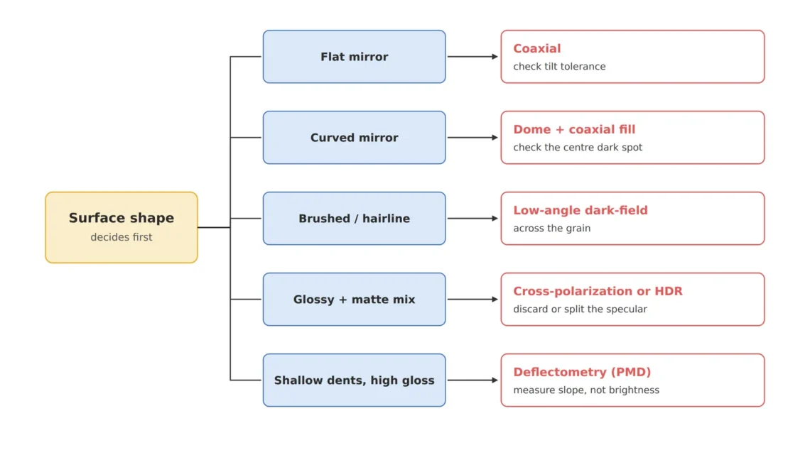
The fix is to split the lighting choice first by two questions: surface shape and scratch shape. This article gathers the lighting approaches covered separately on this site — coaxial, dome, dark-field and low-angle, cross-polarization, HDR multi-exposure — into one selection map of which to try first under which conditions, and links to the detailed articles for the calculations and limits of each method.
The criterion for choosing lighting in metal scratch inspection is not brightness but which direction the surface sends the light back.
1. Flat Mirror Surfaces — Why Coaxial Comes First, and Its Tilt Tolerance
Point. For scratches on flat polished surfaces or mirror-finish covers, coaxial illumination is the first candidate.
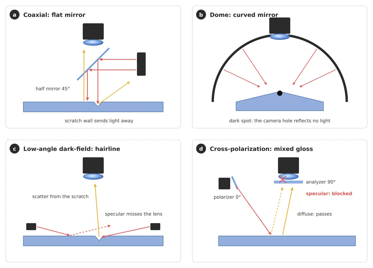
Reason. Light coming down parallel to the optical axis returns from a flat mirror surface into the lens and forms a bright background, while the sloped walls of a scratch deflect the light out of the lens and leave dark lines (coaxial illumination article). This method, however, has a surface tilt tolerance, and whether a diffuser is used changes “from which slope on a surface is seen as a defect”.
Example. In the coaxial illumination article’s setup (75 mm, F5.6 lens), the tilt tolerance was about 0.9° for non-diffuse coaxial and about 5.9° for diffuse coaxial assuming a diffusion spread of ±10°. With a 50:50 half mirror, the light returning to the sensor is at most 25% of the source output.
Point. First calculate whether fixture tilt and polishing waviness fall inside the tilt tolerance, and if they do not, consider the dome in the next section.
2. Curved Mirror Surfaces — Dome Lighting and the Center Dark Spot
Point. For parts that are both curved and specular, such as a convex plated cap, dome lighting is the default, but the center dark spot created by the viewing hole must be calculated.
Reason. A dome turns the whole hemisphere into a light source and supplies light to every direction of a curved surface, but the hole the camera looks through emits no light, so the area that reflects that direction stays dark (dome dark spot article).
Example. In the dome dark spot article’s calculation, without fill light the center dark spot covered an area about 81 px across, and the effective inspection area including the outer ring was 4.24 mm of the 5.0 mm cap radius, about 72% by area.
Point. When using a dome, calculate the effective inspection area before resolution, and fill the dark spot with coaxial fill light instead of covering it with a mask.
3. Hairline and Shallow Scratches — Dark-Field and Low-Angle
Point. For directional machined surfaces or shallow scratches, low-angle dark-field can be the better choice.
Reason. Light coming in at a low angle is reflected specularly by flat areas and misses the lens, and only light scattered where there is a slope, such as a scratch or particle, enters the lens and becomes a bright line on a dark background (dark-field illumination article). On surfaces where the machining grain itself has a slope, the coaxial background fills with the grain, so the difference becomes especially large (the opposite condition in the coaxial illumination article).
Example. The dark-field illumination article covers a configuration that combines dark-field with edge decision logic trained only on defect-free samples, and the software-defined lighting article covers switching between dark-field and coaxial per recipe with a single multi-channel head.
Point. The key is to set the lighting direction perpendicular to the grain, and for parts with defects in several directions, consider splitting captures by direction with quadrant lighting or multi-channel switching.
4. Glossy and Matte in One Frame — Cross-Polarization and HDR
Point. When plated pins and a matte molded housing share a frame, either discard the specular reflection with cross-polarization or capture the two materials separately with HDR multi-exposure.
Reason. Cross-polarization places a polarizer on the light and an analyzer on the lens at 90° to block the specular component whose polarization is preserved (cross-polarization article), and HDR combines several images with different exposures to hold a brightness difference beyond the dynamic range of a single sensor image (typically 60 to 70 dB) (HDR multi-exposure article). The difference is that the former discards information and the latter splits it. As the cross-polarization article points out, metal specular reflection can include a circular polarization component, so the blocking effect varies with material and incidence angle.
Example. Cross-polarization means accepting light loss and a WD margin for polarizing accessories, and HDR requires the part to stay still while several images are taken, or the images to be registered. When the shape itself is the defect, as with shallow sinks 20 to 50 µm deep in high-gloss molded parts, phase measuring deflectometry (PMD), which measures slope directly, can fit better than either.
Point. The criterion is “is the information inside the specular reflection needed?”. If not, cross-polarization; if yes, HDR; if the shape itself is the defect, consider PMD.
5. Core Framework — Matching Table (Lighting Selection Map)
| Category | Condition | Lighting to try first | Value to check · detailed article |
|---|---|---|---|
| ① Minimum defect size | Scratch about 20 µm wide (flat mirror) | Coaxial | About 3.3 px at 6.0 µm/px — coaxial illumination |
| ① Minimum defect size | Pinhole about 25 µm (curved plated cap) | Dome + coaxial fill | About 3.8 px at 6.54 µm/px, effective area about 72% — dome dark spot |
| ① Minimum defect size | Sinks 20 to 50 µm deep (high-gloss molding) | PMD (+ polarization fusion) | Slope measurement — PMD |
| ② Optical setup | Flat mirror, fixture tilt controllable within 1° | Non-diffuse coaxial | Tilt tolerance about 0.9° |
| ② Optical setup | Polishing waviness around 1° | Diffuse coaxial | Tilt tolerance about 5.9° (±10° diffusion assumed) |
| ② Optical setup | Hairline / directional machining | Low-angle dark-field perpendicular to the grain | dark-field / software-defined lighting |
| ② Optical setup | Glossy + matte mix | Cross-polarization or HDR multi-exposure | Sensor dynamic range 60 to 70 dB — cross-polarization / HDR |
| ② Optical setup | WD (working distance) | Each method takes a different lighting height — secure it including coaxial box height, dome diameter and low-angle ring height | dome diameter and WD calculation |
| ③ Algorithm | Handling saturated areas | Suppress saturation with lighting and exposure before filtering | filtering order |
| ③ Algorithm | Filter order | Edge-preserving filter (bilateral) before the defect decision | filtering order |
Table insight. The first criterion that splits the lighting choice is not defect size but surface shape (flat, curved, directional, mixed). Even for the same 20 µm class scratch, the first candidate switches from coaxial to dark-field when the surface becomes a hairline finish. And because each method requires different lighting space inside the WD, if two or more lighting candidates remain, it is safer to reserve space for both at the mechanical layout stage.
6. Conditions Where the Opposite Approach Wins
- Metals with a diffuse finish such as bead blasting: specular reflection is weak, so coaxial cannot form a bright background, and angled lighting is more economical in both light level and contrast.
- When the defect is color or discoloration rather than shape: wavelength selection can work better than lighting angle (wavelength selection article).
- When single-direction lighting already gives enough contrast: methods that use more space and capture time, such as dome or HDR, are overkill.
The reflective properties of metal surfaces vary widely with polishing conditions, coatings and oxide films, so which lighting is better cannot be guaranteed before a sample test.
Field Note
In an inspection with plated connectors and a matte housing in one frame, I first held on with filter combinations, but the scratches on the saturated pins did not come back with any filter. Once I split the surface into flat mirror, curved mirror and matte, and rewrote the lighting candidates for each area, it became clear that the pin area needed coaxial and the curved shell needed dome fill light. In the end we moved to a configuration that captures twice under separate lighting conditions and redistributed the inspection time. The lighting-per-area table made then is the starting point of the matching table in this article.
Field Checkpoints
- Is the space for the candidate lighting secured together with the WD? — check with coaxial box height, dome diameter and low-angle ring height all included.
- Was the surface first classified as flat mirror, curved mirror, directional machining or mixed?
- For coaxial, do fixture tilt and polishing waviness fall inside the tilt tolerance?
- For a dome, were the center dark spot size and the effective inspection area calculated?
- Was saturation suppressed with lighting and exposure before handling it with filters?
- Metal reflective properties cannot be guaranteed before a sample test — were comparison images taken per method with limit samples?
Related reading — How to Handle Imaging on Highly Reflective Surfaces · Six Machine-Vision Lighting Methods and How to Choose · Is Coaxial Light Enough for Fine Scratches on Polished Metal? — Redesigning Coaxial Illumination Around Half-Mirror Loss and Tilt Tolerance · Specular Reflection Erases Defects: How Cross-Polarization Catches Missed Detections on Highly Reflective Surfaces

Noctvision
A machine vision engineer who fits cameras, lenses, lighting, and image-processing algorithms together for a living. Years spent on continuous production lines, vibration, heat, and dust included, working through diffuse reflection, contrast, and resolution differences too fine for a spec sheet to capture inform every post here, closing the gap between theory and the shop floor. Off duty, that same eye for light and lenses goes into repairing fully mechanical vintage film cameras.


You May Also Like
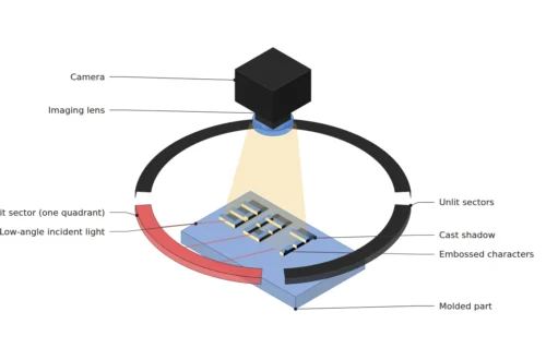
Why Does One Lighting Angle Decide OCR Read Rates on Molded Characters? — Low-Angle Ring Illumination and Quadrant Lighting Calculated from Character Height and Stroke Spacing
Software-Defined Lighting: One Head, Switching Between Dark-Field and Coaxial Illumination